08
Development:
Automata & Table Setup
~ 07.03.2025
Pepper's Box
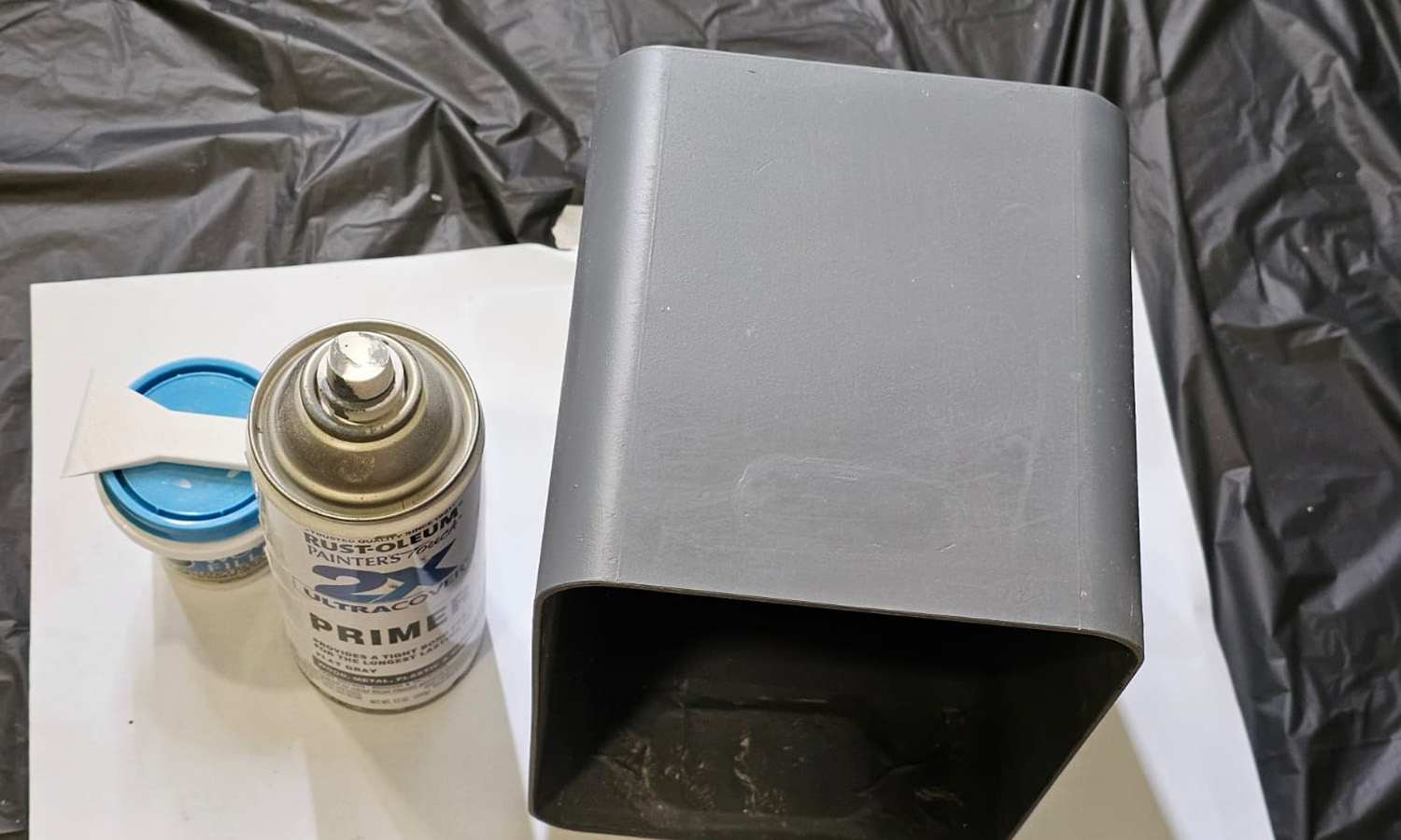
Picking up from where I left off last week. I mentioned that I was printing the inner structure. As such, I was planning to use a 3D-printed frame to create the upper structure. I then chose a suitably sized plastic box from a discount store and used a glue gun and wood putty to fill in any gaps, primed it with gesso, and so on. However, once the 7-inch screen arrived and I mounted it, it no longer fit inside the box—so I scrapped the 3D print. I decided to build the inner structure out of foam board instead.
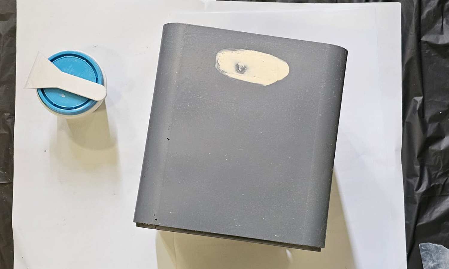
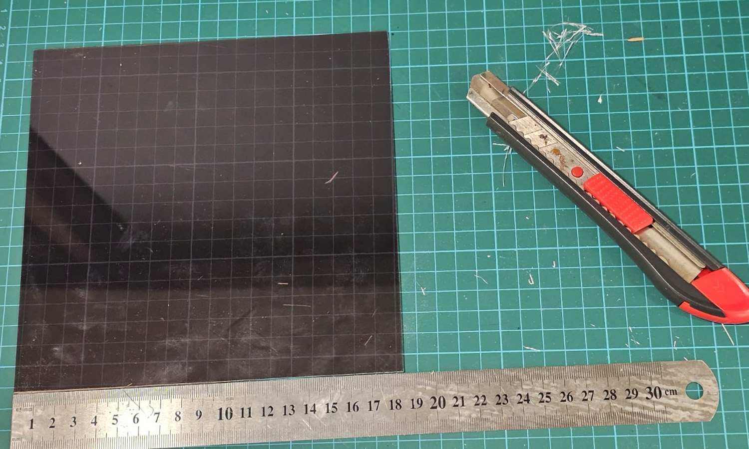
I originally planned to make the hologram box out of 5mm black foam board, but I was worried it wouldn't be sturdy enough. I discovered that 2mm A5 MDF boards were just the right size, so I used them for the base and sides. The back panel was slightly larger and wouldn't have to support much weight, so I used foam board for that.
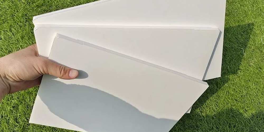
To hold the acrylic panel at a diagonal inside the box, I cut the foam board diagonally and attached it to the inside of the wooden side panels, creating a groove so that the acrylic sheet could slide in.
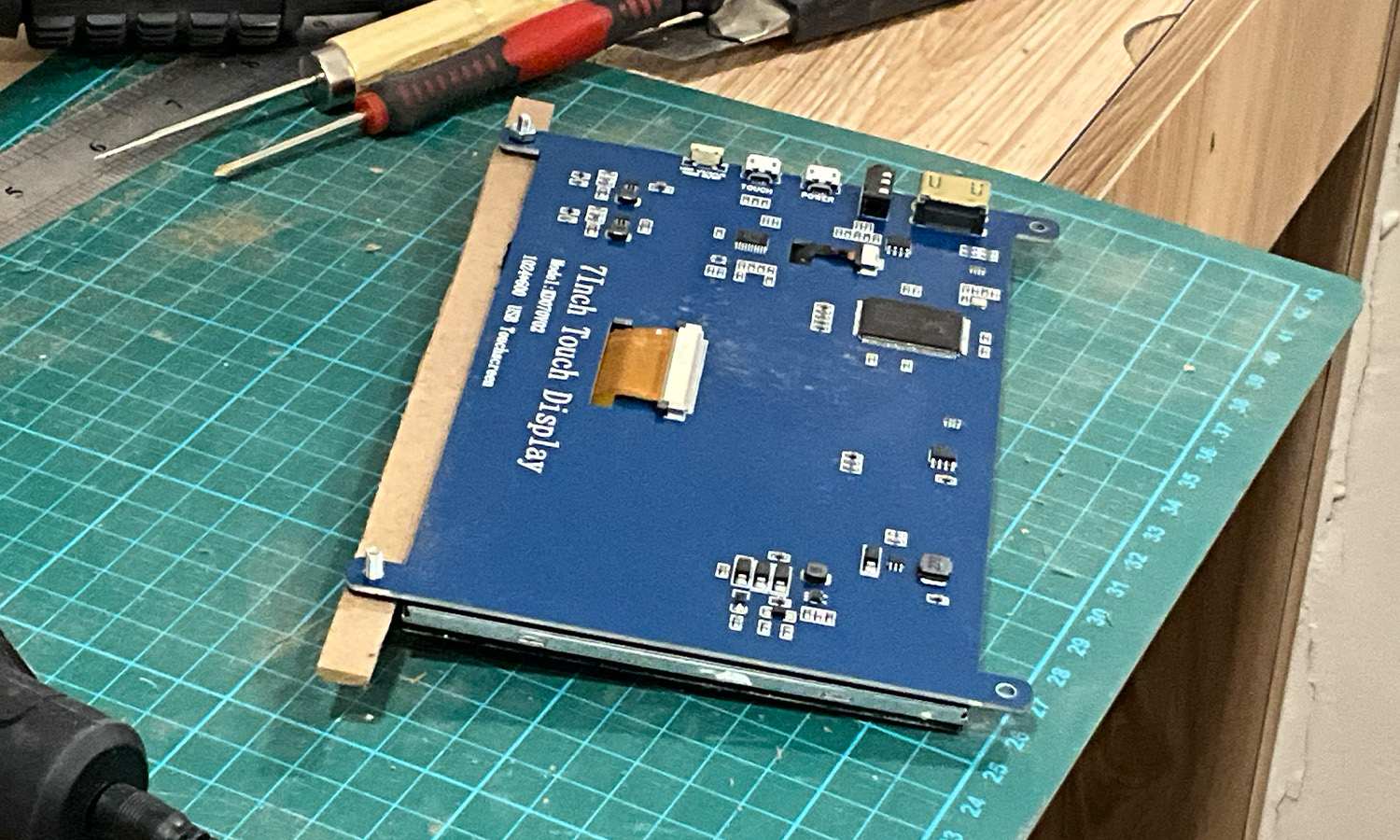
The screen has two screw holes each on the top and bottom. I cut the MDF board longer than the screen's width so I could fasten the screws there and then rest the board across the two vertical supports.
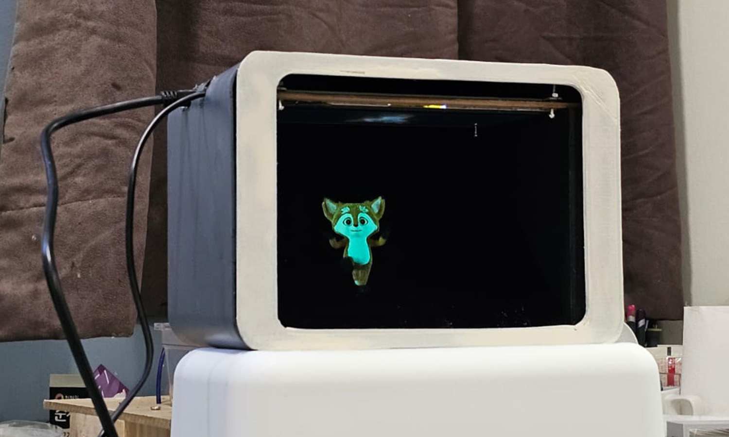
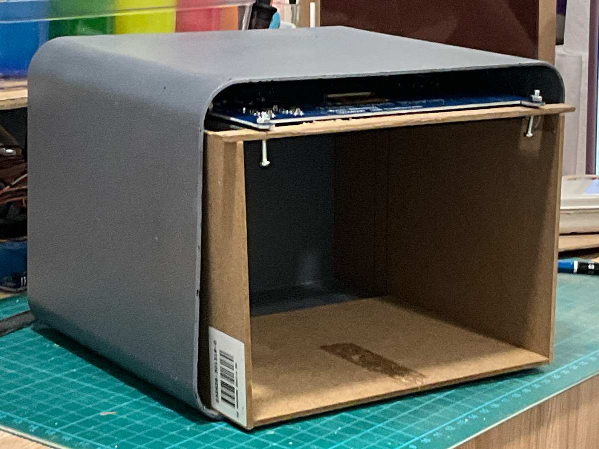
After placing the structure into the box, I checked where the holes for the HDMI and 8-pin connectors should go. I used a soldering iron to melt holes in the box and then a grinder to smooth the edges. I plan to secure the inner box with a glue gun and Styrofoam, then 3D print the front panel and fasten it in place.
Change of Plans
While trying to find an appropriate visual for the pepper's box, I decided it would be best if I use it as way to display the audiovisual experiment rather than be a part of the prototypes. It didn't feel justified well enough by any possible concepts. Like I mentioned last week, I had encountered an issue that I outlined as a critique on 'reverse engineering' in week 0 of this semester. So the pepper's box will be a part of the experiments presentation in open studios.
This way, I can resolve another concern I've had. I've been considering the scale of my work and the possibility of using an Axidraw or a projector. While both could produce interesting results, they don't really fit with the series of outcomes I have in mind, and I value the personal touch of a hand-crafted interface. Also, with around 80 other students sharing space during open studios, using a projector might come across as excessive or pushy. I want to be confident in the quality of my work, and I don't want to rely on sheer size or spectacle to draw people in. With pepper's box, I can add a certain effect to the audiovisual experiment that negates these concerns.
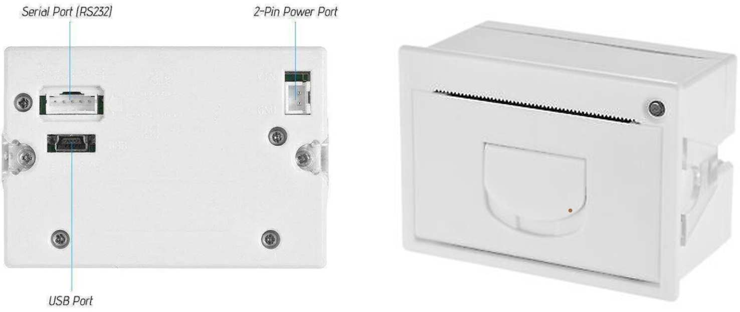
My potential additional prototype will instead use the thermal printer like I had originally planned. Using a thermal printer to print a bitmap image sent from Processing in real-time when a button connected to an Arduino was pressed. The EEG data can generate an evolving image displayed on a secondary screen. When the button was clicked, the image would be saved and transferred to the Arduino for thermal printing as a bitmap.
A second idea is an interface where the screen—approximately the width of a receipt—is placed on the left, while the opening of a thermal printer is positioned directly on the right, creating a gradual transition between digital and analogue. This is a simple yet effective concept that could work well. So this is what I am open towards at the moment.
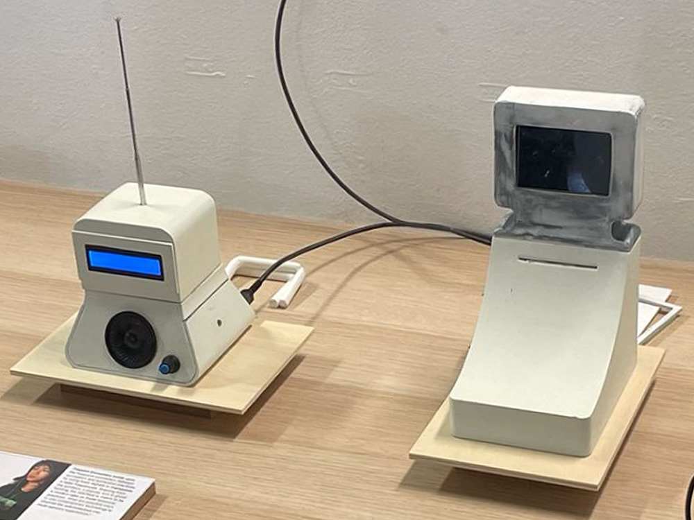
Automata
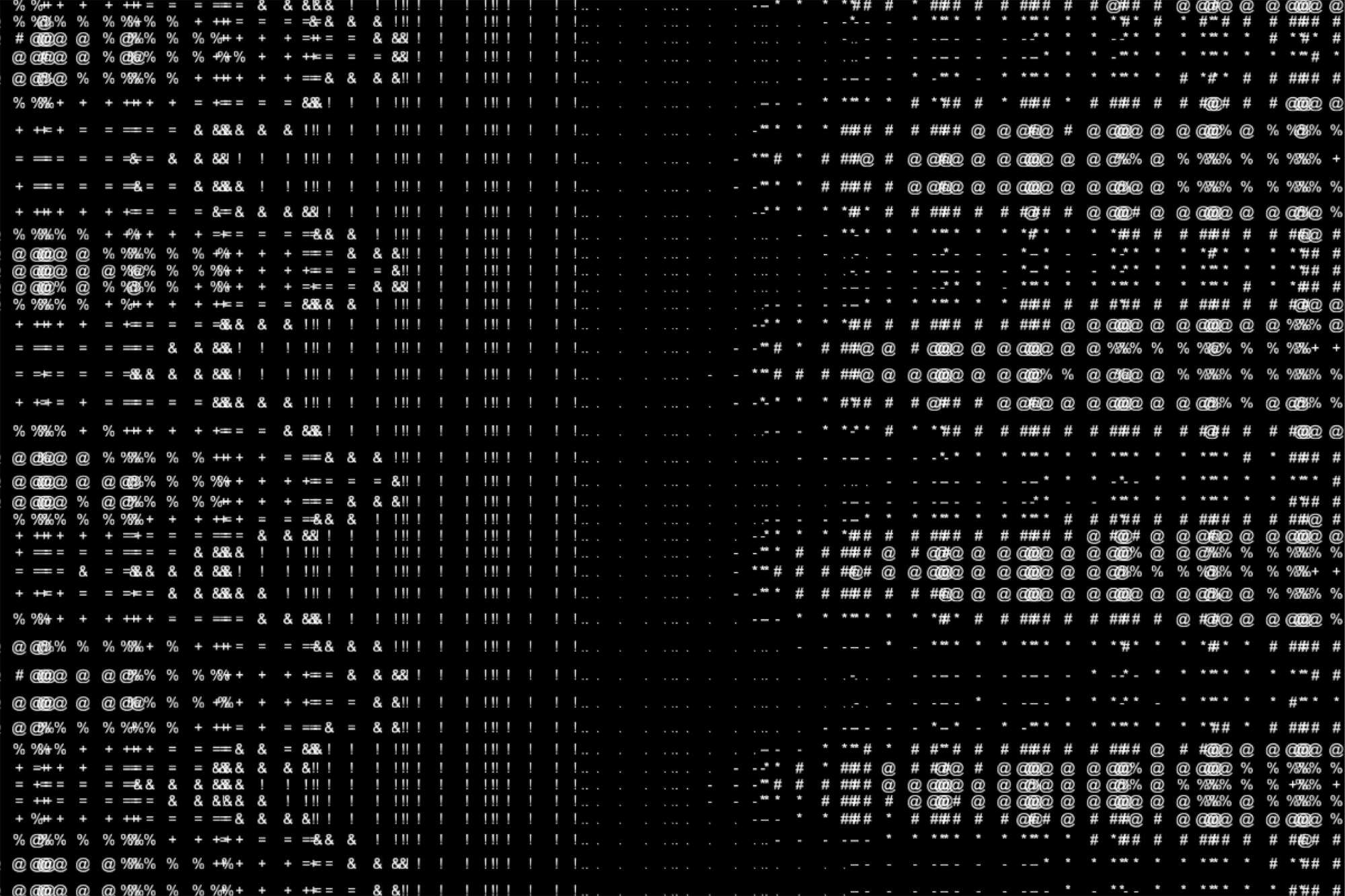
So after some consideration, I decided to create Automata, an additional interface that translates alpha and beta waves into abstract bitmap images. Inspired by the practice of automatic drawing and the surrealist fascination with mechanical devices as extensions of the unconscious mind, this experiment creates a visual "graphic trace" of neural activity. Alpha waves guide the , while beta waves influence its, automatic drawing's.
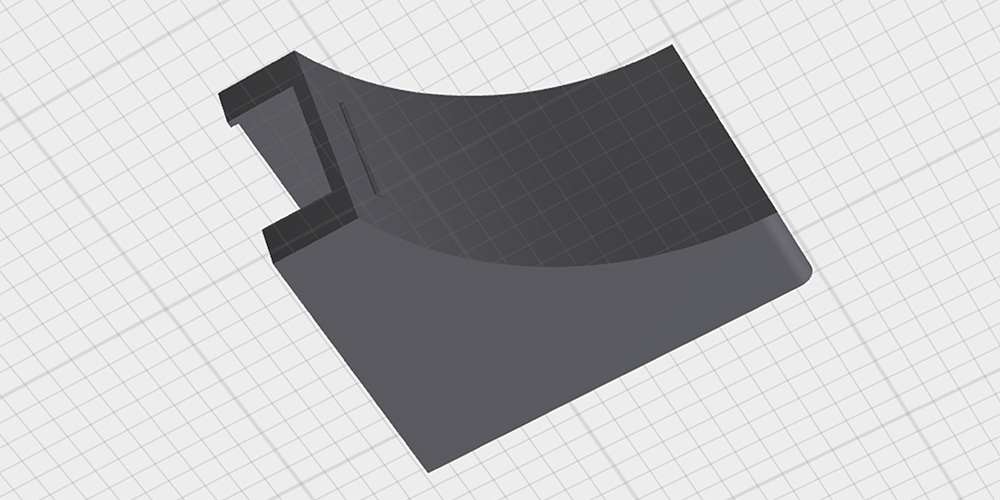
Like the other interfaces, I rounded the edges to align with the overall visual identity of my website, which complements the concept. The basic considerations were functionality and practicality, so that each component could fit in nicely while the user's eyes would be guided from the screen to the printing outcome. Not much needed to be done once the print was ready.
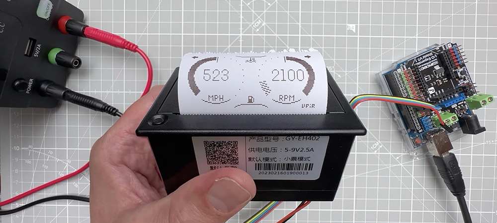
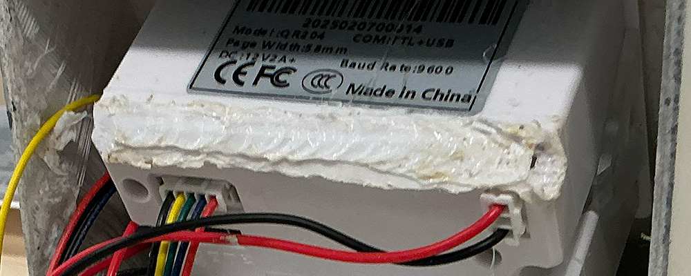
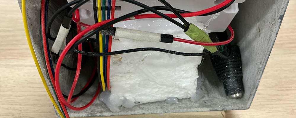
I needed to align the height and angle of the printer's paper output slot with the corresponding opening in the case. To ensure stability, I cut Styrofoam into a chair-like shape to support the printer and secured it in place with a glue gun. Unexpectedly, the lower back part of the printer extended beyond the case more than I had anticipated, so I used a soldering iron to flatten and adjust the surface.
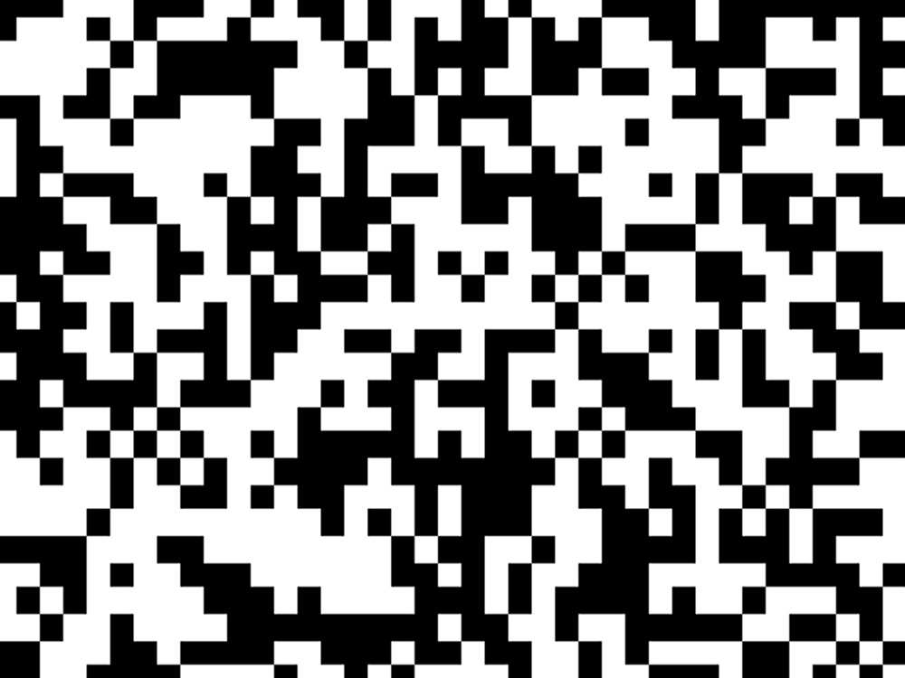
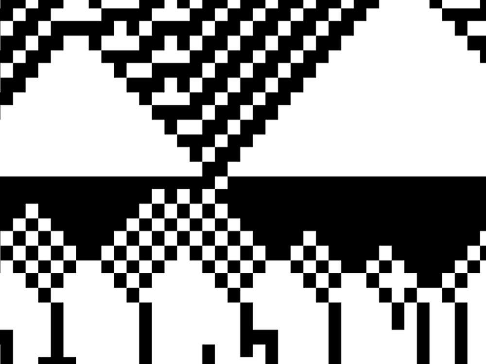
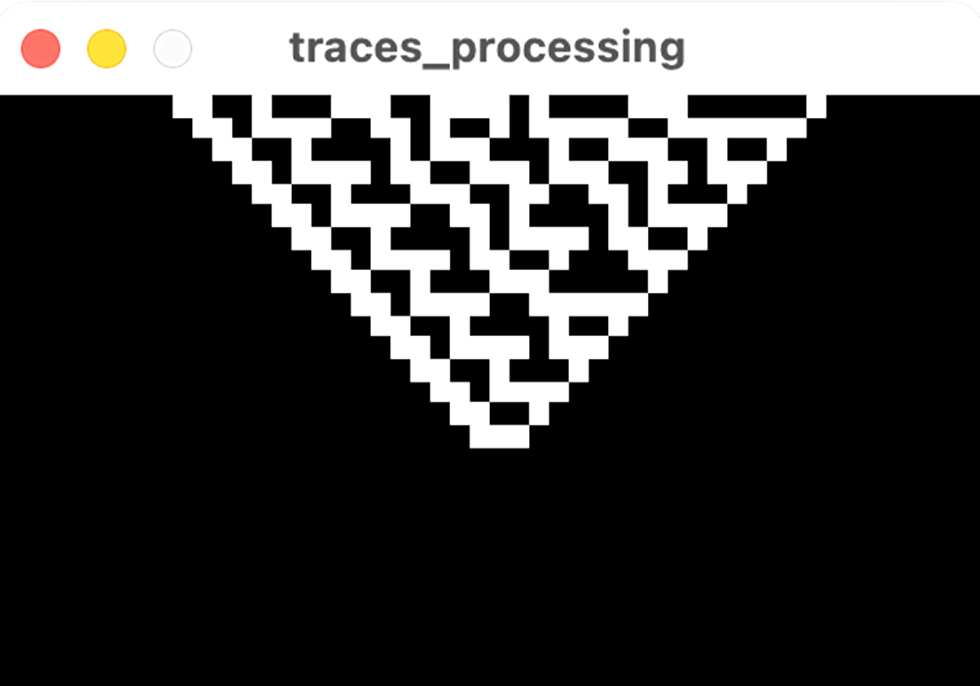
In terms of the coding, I used cellular automata to generate bitmap patterns because it's a straightforward way to simulate complex, evolving behaviour using simple rules. I set the rule to Rule 30, for its iconic and varied patterns, though this rule can be changed later on.
For the mapping, I derived the perturbation and injection chances from theta wave measurements. This means the randomness and amount of white tiles is directly influenced by the user's level of relaxation.
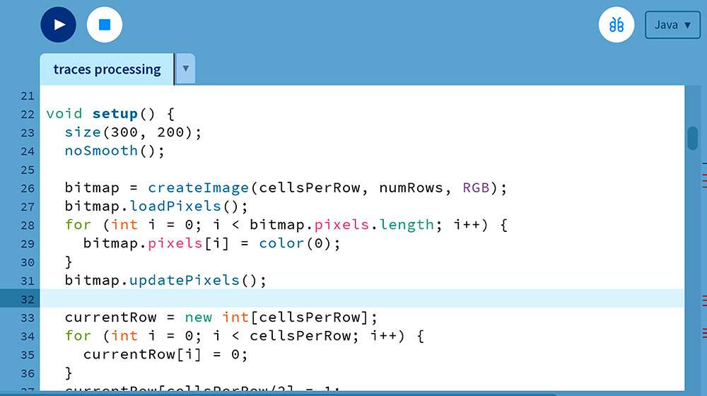
A new CA row is computed every 250 milliseconds and inserted at the top of a scrolling bitmap. As new rows appear, older ones shift downward until they disappear at the bottom, as a real-time representation of the evolution.The disappeared patterns are printed onto the thermal paper, creating a continuous scroll of patters.
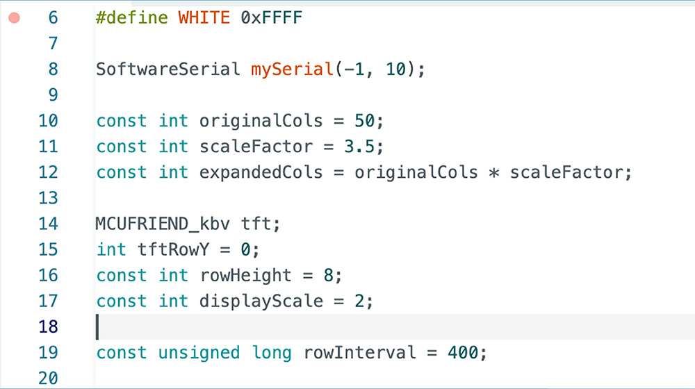
To execute this (connect the digital visualisation with a physical output), I used serial communication to send each new row—as a string of 0s and 1s—to an Arduino-controlled thermal printer. On the Arduino, a sketch listens for incoming serial data and prints each line immediately.
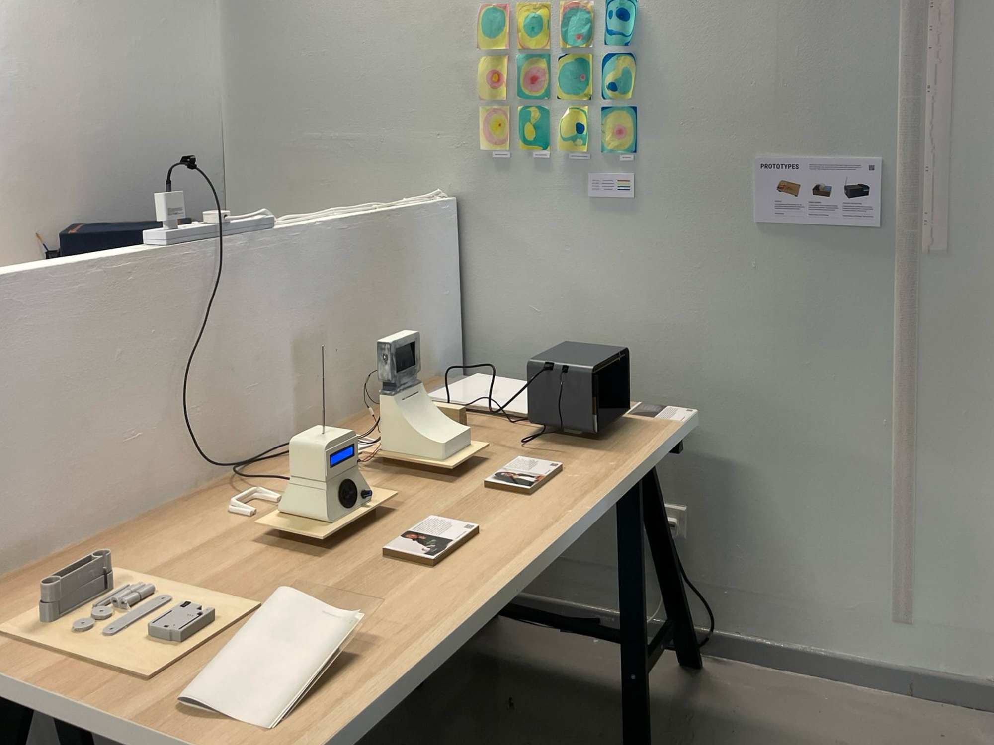
Table Setup
For a sort of mid-term review, my peers and I were to setup a table presenting the outcomes from term 1 (I joked that we could print out our dissertations and present that as the main item). My table was quite straight-forward. The three prototypes in progress and a simple booklet to show the interview results from artist Yeo Shih Yun. I also considered adding my graphic explorations to the table as prints, but just opted for a digital display on my laptop since there weren't any good examples for how they might be applied in use.
Andreas mentioned that he prefers the aesthetics of my Semester 1 outcomes, and I agree—I like the industrial, makeshift look. However, I still stand by my current outcomes because they align with my vision for a graduation project: more professional and polished. Regardless, I will need to rebuild my previous outcomes for Open Studios, which will allow for an interesting comparison.
One remark from my peers was that while they like both outcomes (possibly out of courtesy), each conveys a different narrative. The Semester 1 outcomes, with their makeshift appearance, feel like they were created by a "mad scientist," whereas the current outcomes look more corporate. I don't think my wavelet prototype would work well as a 3D-printed interface. The appeal of the interface itself is the "mad-scientist" look.
This is a new concern because I initially believed that both designs had a retro, 20th-century form rather than a modern look. But after my peers comparing my semester 2 outcomes to very modern, sleek, and stylish designs—like Apple's, I'm a bit worried for the overall cohesion. For now, I will continue with Wavelet in a more makeshift style, but I might change it after Open Studios depending on the feedback.