07
Version 2.0:
Frequent Encounters & Pepper's Box
~ 30.02.2025
The Radio
This week marked the official start of my final prototyping phase. The first project I revisited was the radio interface, which had been on hold before the dissertation. The form was decided based on aesthetics and functionality. For example, 20th century machines and computers, which reflect the timeframe of my research on surrealist automatism. I had already modelled and 3D-printed the interface and had made some attempts to polish the surface.
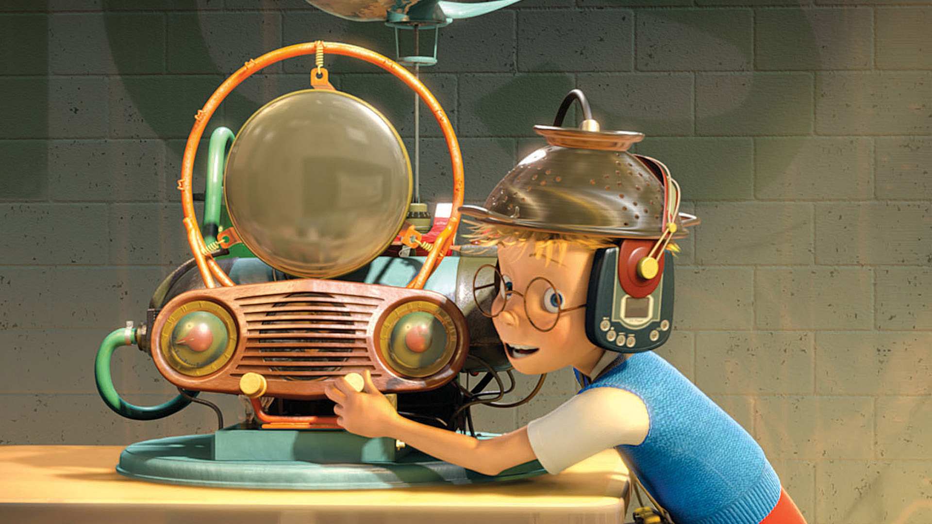
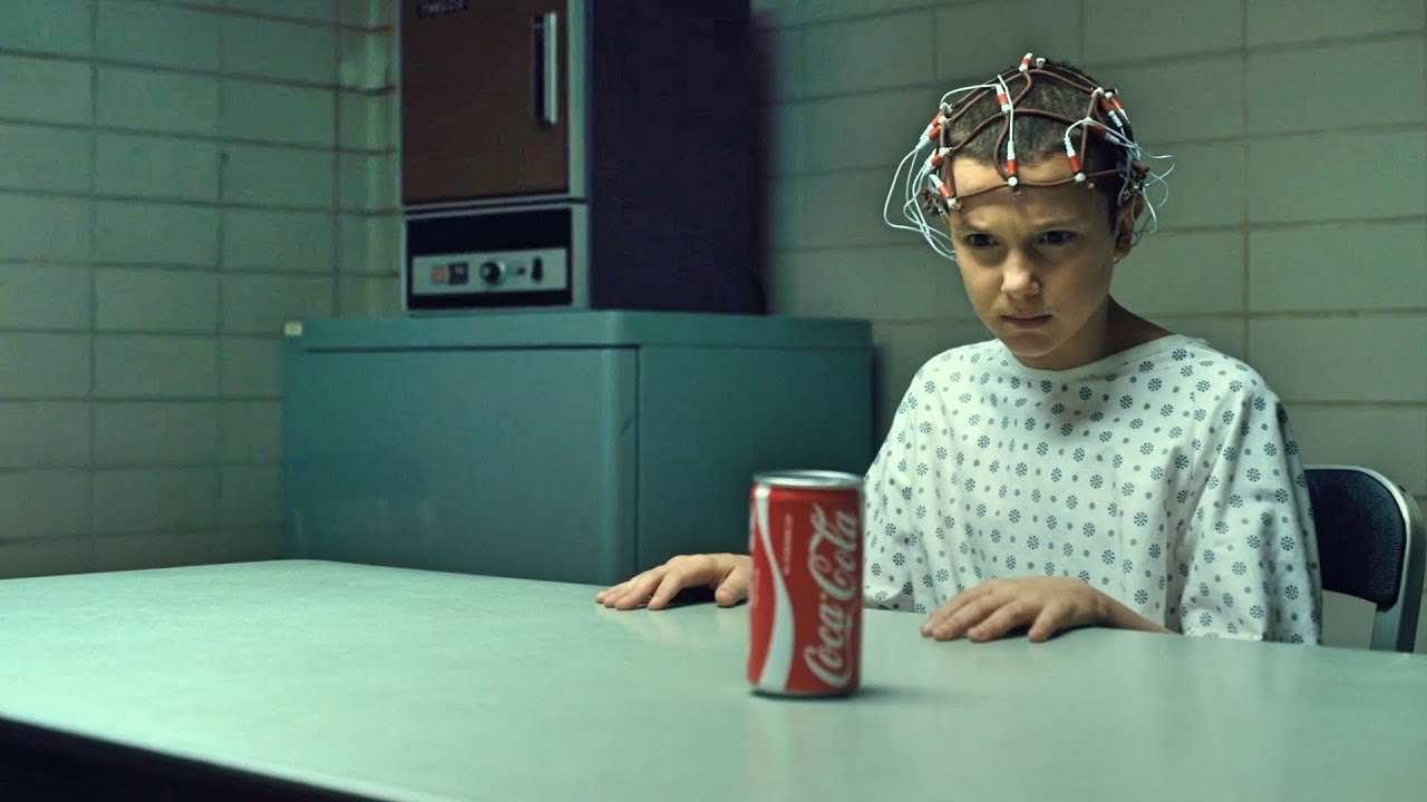
Although I wanted to develop the interface further based on the user feedback, there weren't any negative comments about the radio itself. While some users expressed confusion about the concept, once I explained the backstory, they saw it as a novel exploration. Many mentioned it was worth experiencing, with one person even saying they felt like a movie character—which I found amusing. Overall, it was one of the more appealing concepts so I didn't need to make drastic changes to the mapping.
I removed the printer component, as it will be part of a separate interface, and added a volume knob after users mentioned the sound was too loud. Previously, the speaker volume couldn't be adjusted and was always too quiet, so I had to rely on earphones. I attempted several fixes at the time but couldn't resolve the issue. This time, I installed a separated audio jack to enable both headphone and speaker output.
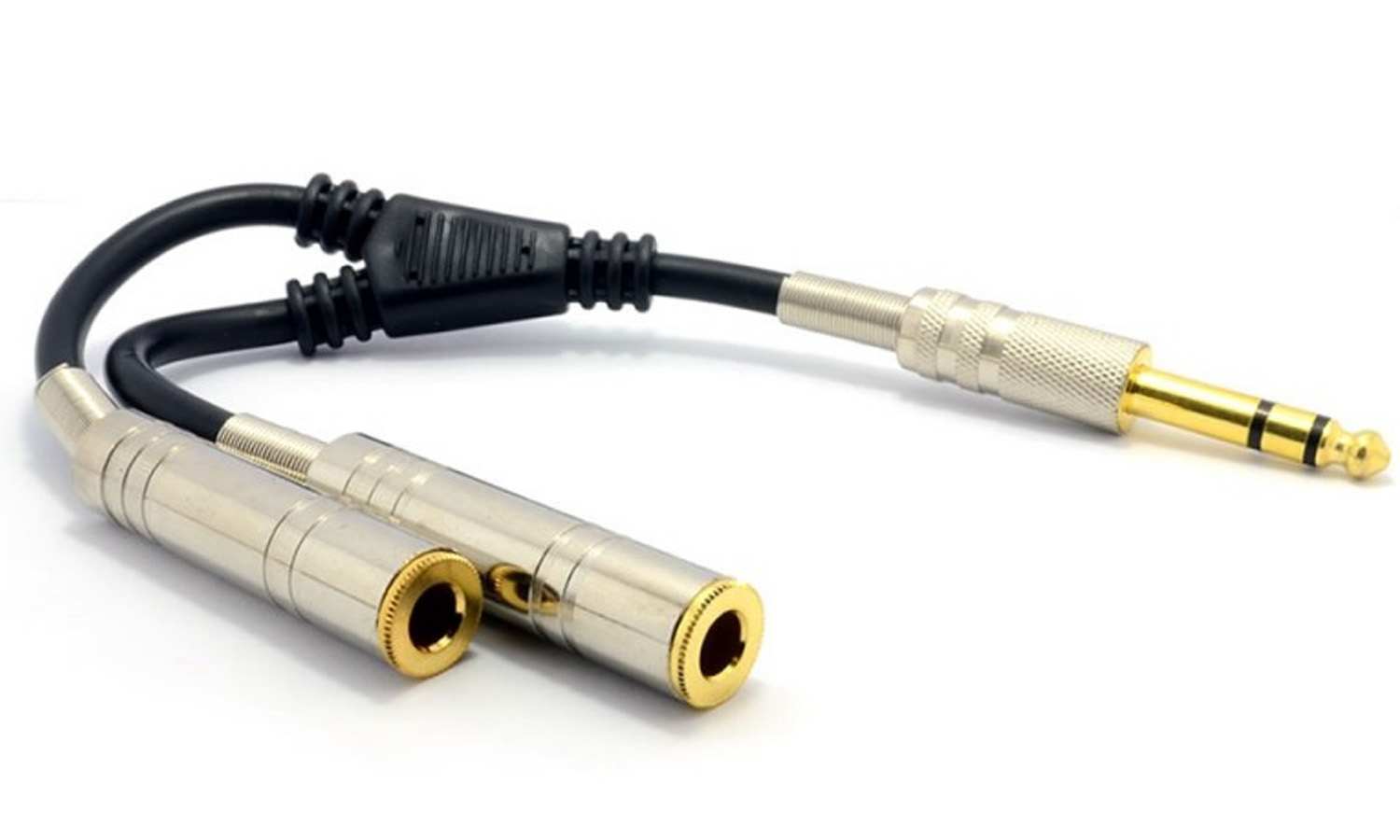
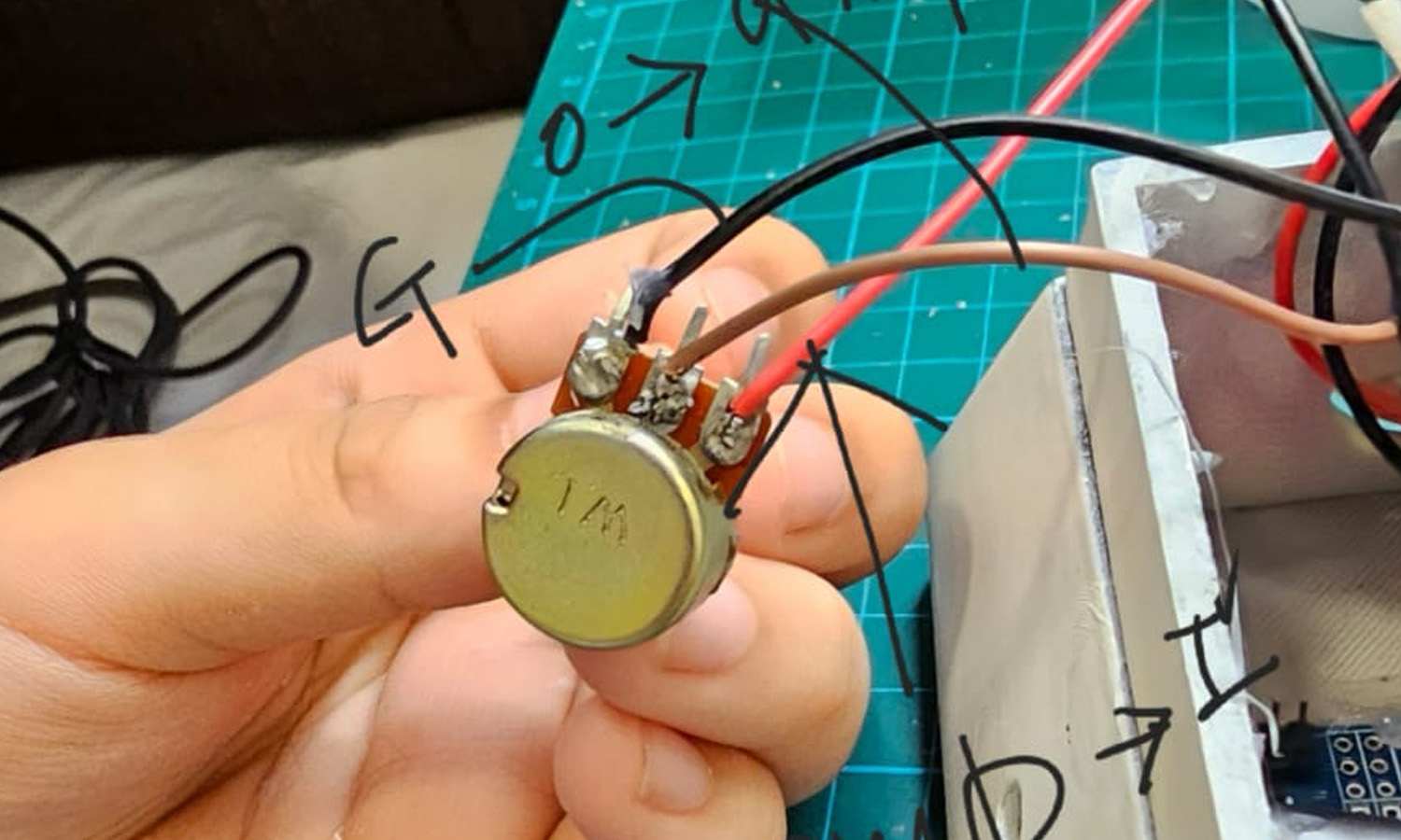
I connected a dual-gender adapter (one male 3.5mm jack to two female 3.5mm jacks) to the TEA5767's audio output. Initially, I had used a splitter that separated the mic and headphone signals, but I replaced it with this setup. One port was used for earphones, while the other was connected to the amplifier, a resistor for volume control, and the speaker.
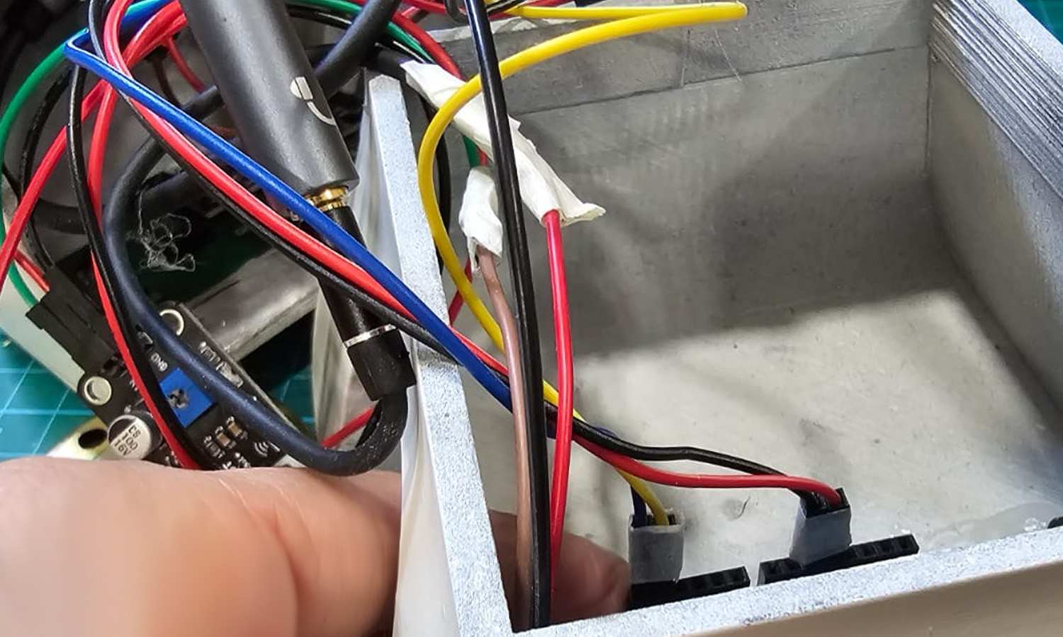
For the wiring, I connected the TEA5767's red wire to the LM386's input (which includes the volume knob) and its gold wire to ground. The LM386's positive and negative terminals were then linked to the corresponding terminals on the speaker. To incorporate volume control, I routed the red wire from the TEA5767 through the resistor before connecting it to the LM386's input, while the gold wire was connected to the LM386's ground.
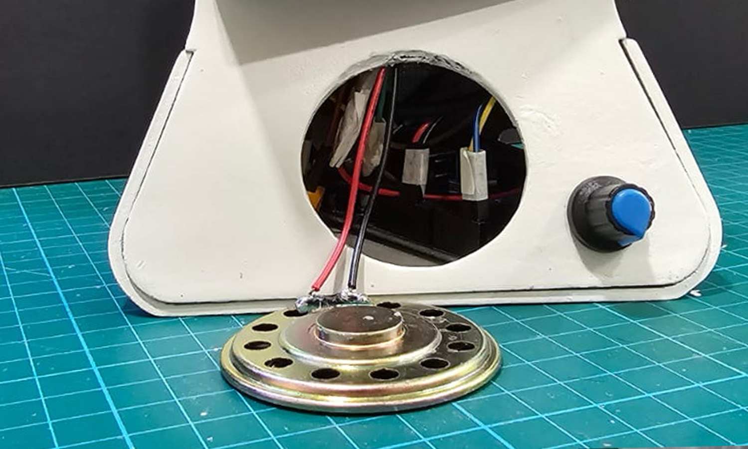
During this process, I found that cutting and preparing the audio cable made it difficult to connect to jumper wires, so soldering was necessary. After confirming that the radio was functioning properly, I secured the components inside the case. However, the connections became loose, causing the speaker to stop working. While troubleshooting step by step, I discovered a 3.5mm male AV screw terminal jack, which I purchased to create a more stable and straightforward connection. Ultimately, I found that the issue was actually caused by a loose connection elsewhere. Once fixed, everything worked properly, confirming that both soldering and screw terminals were more stable methods of connection.
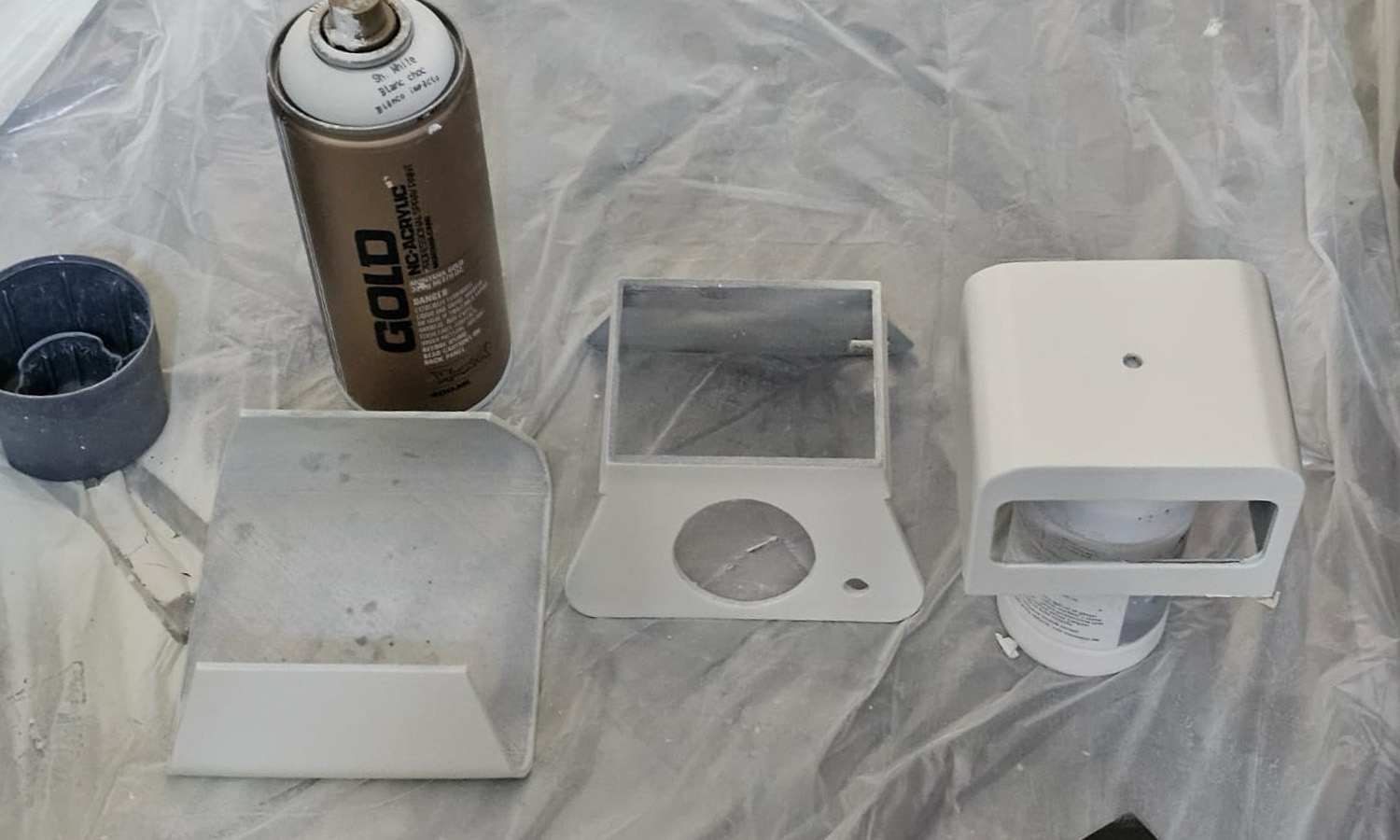
I continued with a few more rounds of sanding and smoothing the surface. The interface's colour, which I seem to have forgotten to mention in previous entries, was a natural cream white, with the knobs and other components acting as accent colours. I envision a vintage computer aesthetic, but I can't fully judge how it might look until the polishing is complete. So, the final colour scheme is still somewhat open to change.

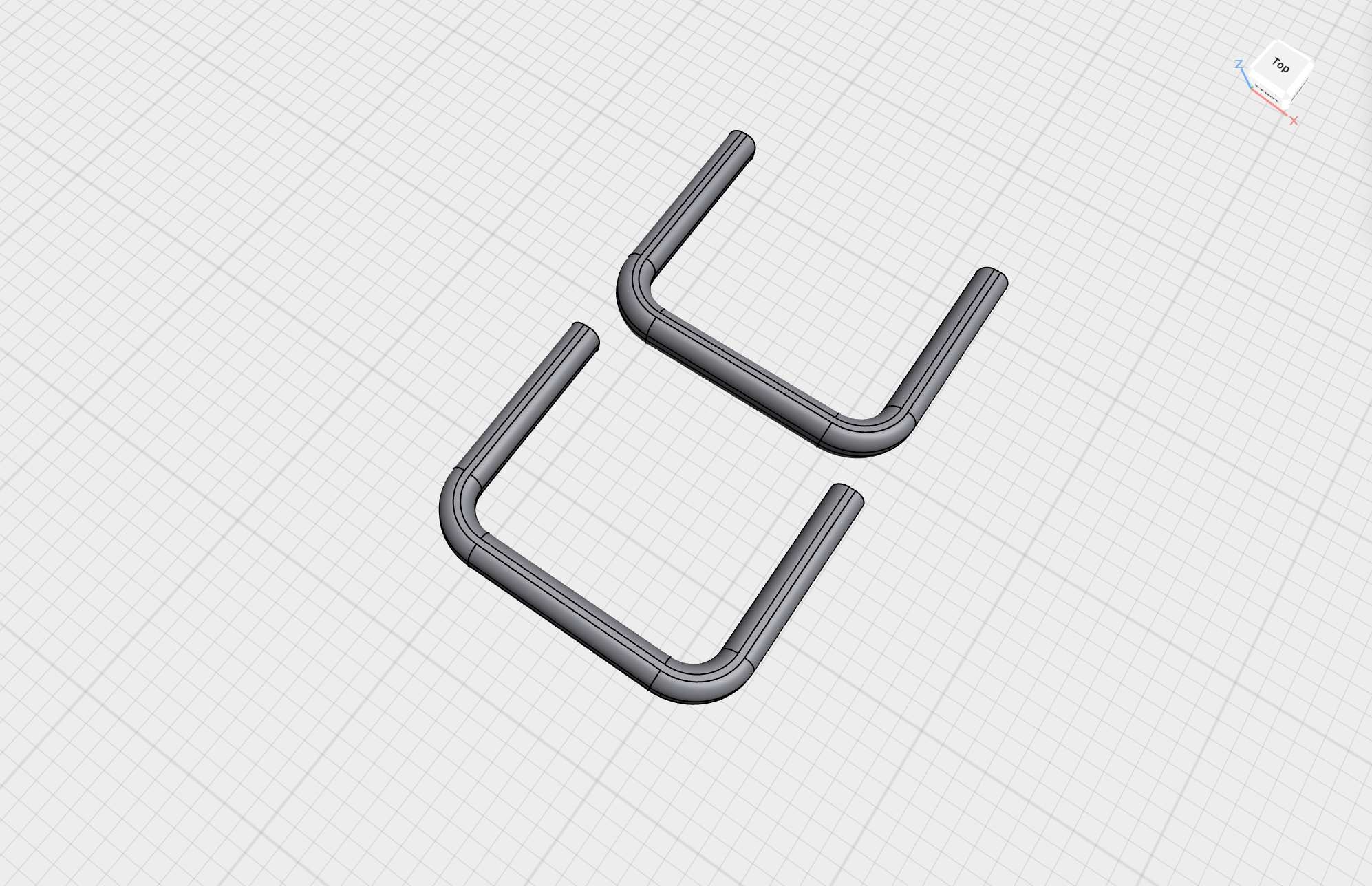
In my previous entry on the initial sketching phase, I mentioned considering a wooden pole underneath the interface. However, I realised that the rounded corners at the bottom did not visually match well with a straight pole. Instead, I decided to create another 3D-printed component—a plastic pole with rounded corners. There are two on each side, resembling the conveyor belt legs of a robot. Some of the feedback I received along the way included comments on what the interface reminded people of, with comparisons to Wall-E or a stormtrooper helmet.
Graphic Interface
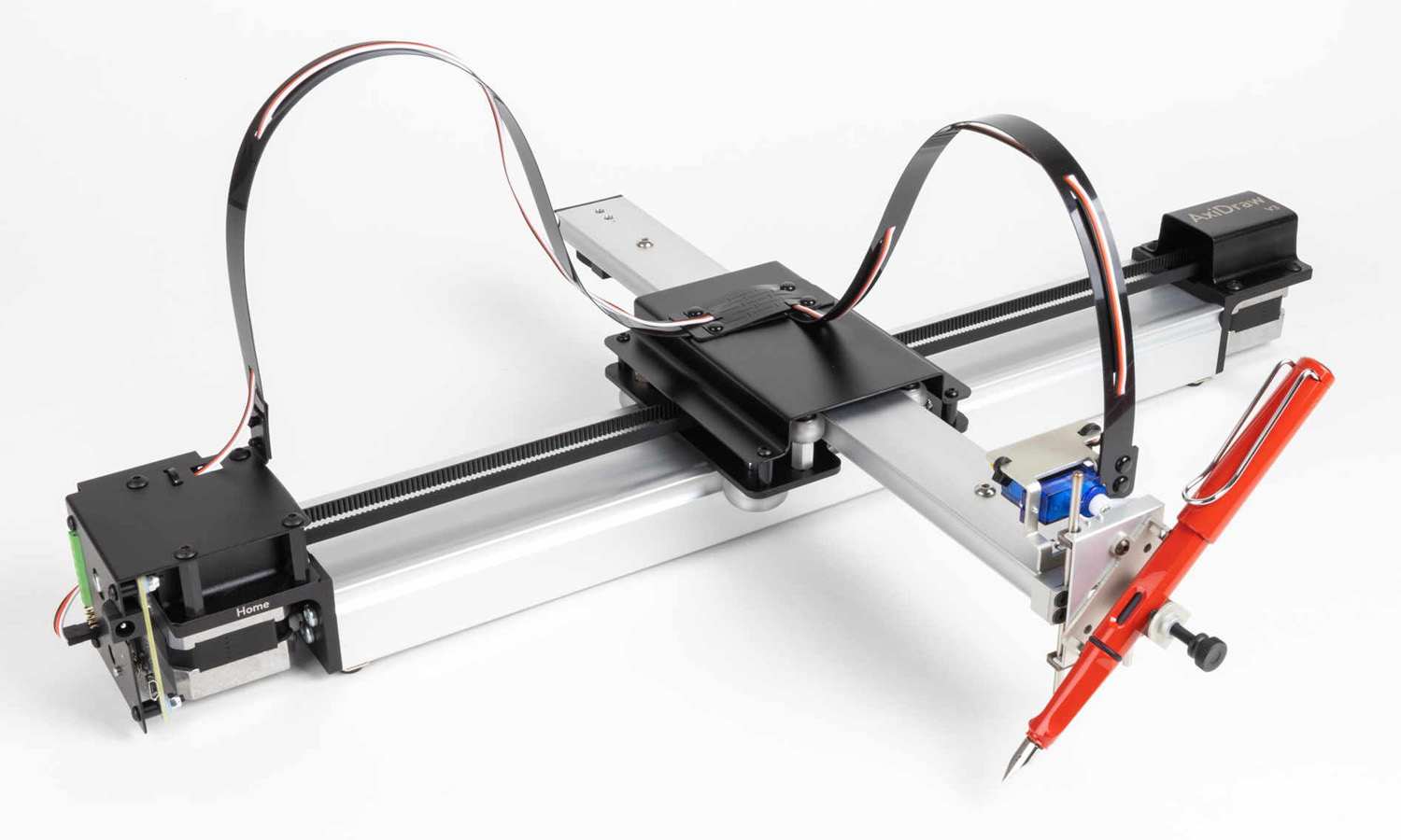
The second interface that branched from Frequent Encounters, which is the print element, was initially planned to be another pen plotter. I considered using a proper AxiDraw for this purpose. However, since the other prototype, Wavelet, is already a larger piece than the others, having only two 3D-printed interfaces and two bigger installations might disrupt the cohesion of the series.
From a curatorial perspective and in terms of how I want to document these pieces in my portfolio, I would prefer a more concise interface for the graphic component. Including an AxiDraw among the custom interfaces could be distracting. Instead, I would rather create a dedicated display for the graphics.
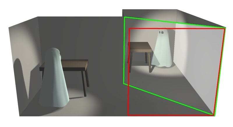
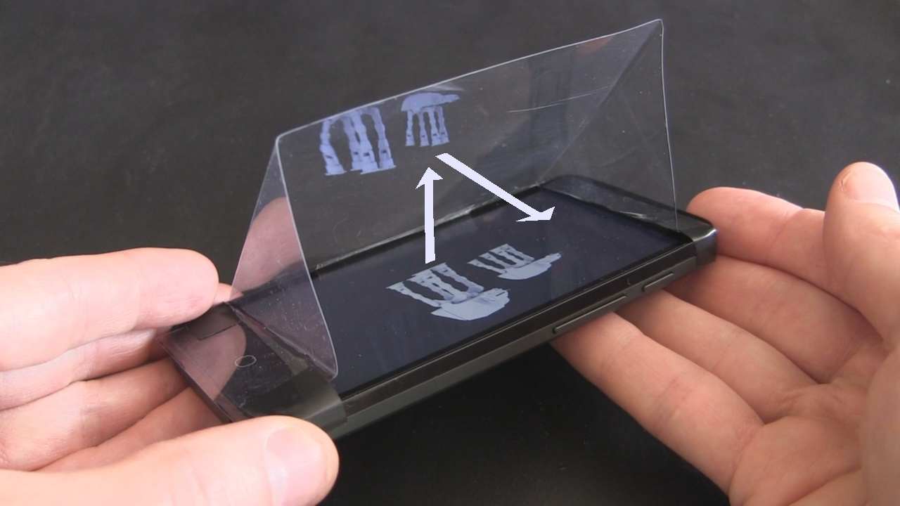
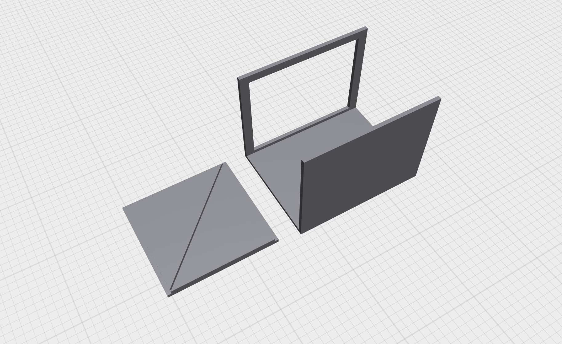
I want it to be more than just a screen. I plan to develop a display based on the pepper's ghost technique. It can create the illusion of a 3D image floating in space using light, transparent surfaces, and reflections.
I am interested in making a box with a digital screen that projects content onto an angled transparent surface (like glass or acrylic), reflecting the image to produce a holographic effect. It would be like a mini theatre.
Initially, I considered a printer to produce real-time prints as the mind "draws." My original idea was for the printer to slowly generate the output, similar to a dream journal, while the visuals remained simple line drawings. But is Pepper's Ghost even suitable for this kind of visual representation? The Pepper's Ghost technique works best with three-dimensional objects, which would be easiest to achieve using TouchDesigner.
That could be an alternative. In that case, a display alone might be sufficient. I need to explore whether I can use the pepper's ghost technique for the line drawings to get the visual depth I want or if I should reconsider the role of the printer in the installation. I have encountered the consequences of 'reverse engineering' that I mentioned in my first entry of the semester.
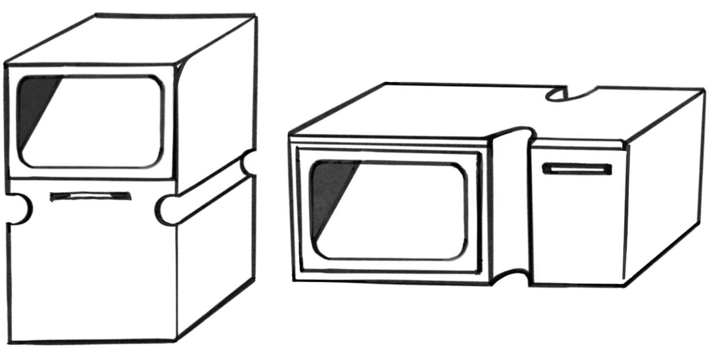
When deciding whether to position the printer on the side of the display (to align with the natural left-to-right reading direction) or at the bottom (to guide the viewer's gaze downward), I sought feedback from my peers.
They felt that placing the printer to the side distinguished it from the Dream Journal design, which had a similar appearance. Interestingly, they mentioned that it resembled a microwave, which they meant as a positive observation.
But then I realised that the interface does not need to be a single whole. The printer can be a separate component. This might be a better approach. It feels less like a product and more like an installation. Now the sketch has been upturned, so that the position of the display and the printer does not matter for now. So my current plan is to focus on creating the display first and add the printer component later if needed.
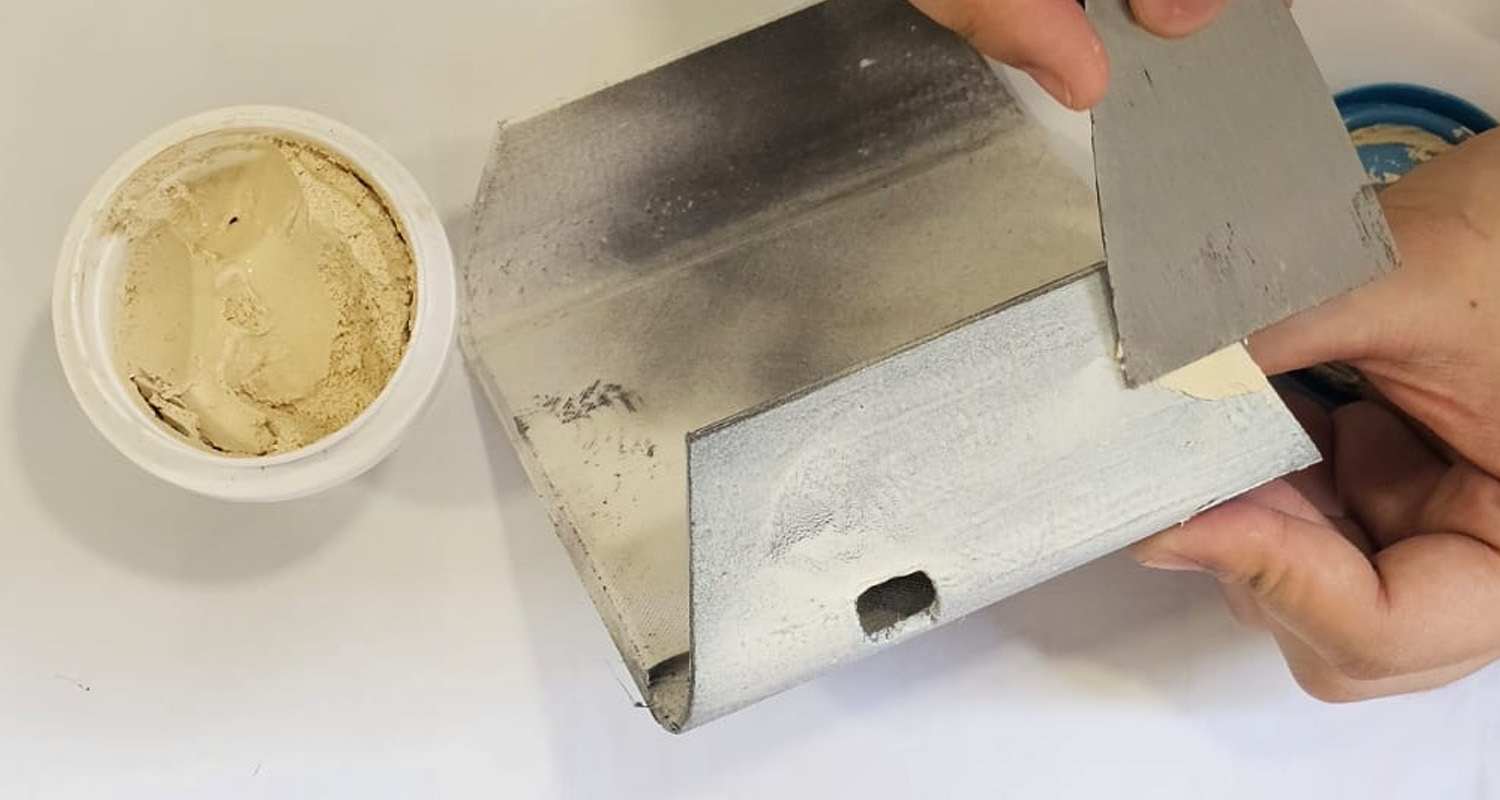
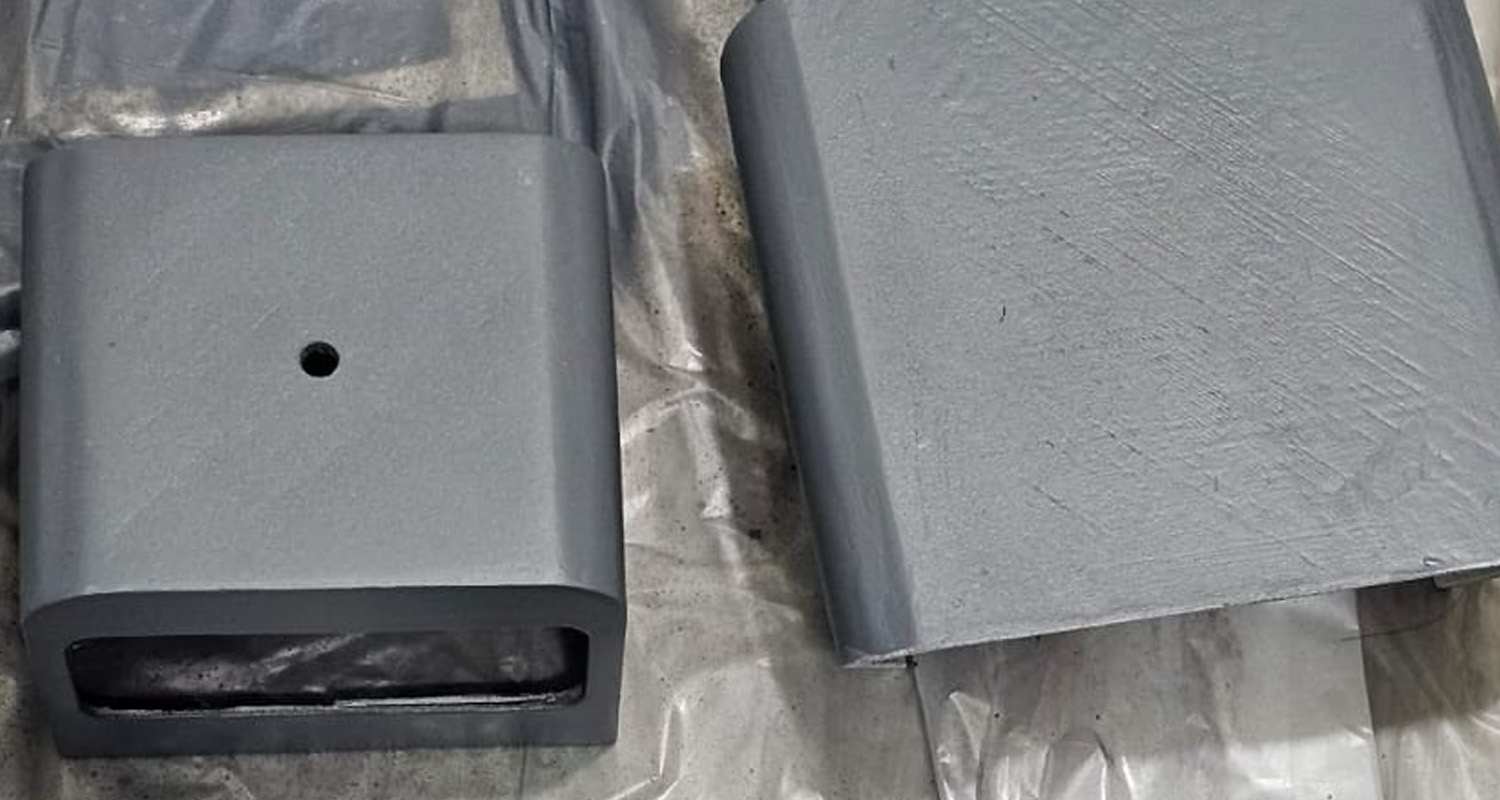
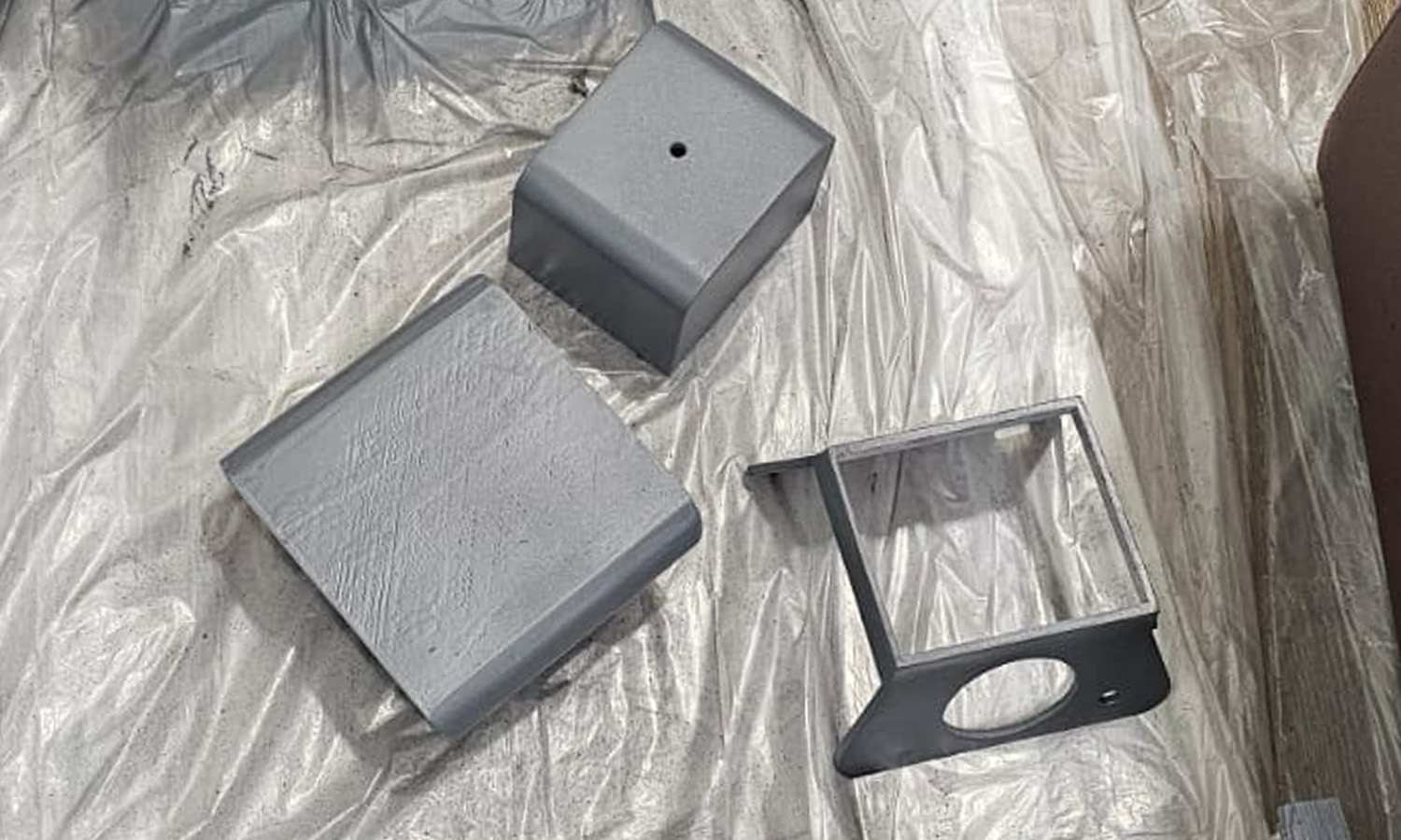
This week, I modeled and printed the inner structure. Once the internal components of the box are finalised and the dimensions are accurate, I will proceed with designing the outer casing, which will hold the LED display securely and connect to the printer casing. This will be continued in the next entry.